his section is accessible to Admin Users only. They will be able to manage, set up, and get detailed information about their project.
Network Page #
This page gives an overview of all the Geocubes and Geoports, their status, and the state of their computation.
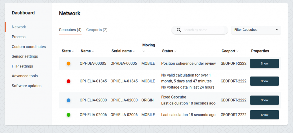
The state column represents the General status of each Geocube. The status field gives more details.
- Green: This means Everything is nominal
- Orange: This means a non-critical problem is affecting the Geocube. Depending on the installation, this can be :
- A low voltage problem: The Geocube might need a battery replacement soon
- Low radio quality: The Radio link of this Geocube might be weak and need to be improved for the good operation of the Geocube system
- The Computation Algorithm is checking the position of the Geocube. Different reasons can lead to such a state: a large movement, a bad satellite situation, etc.
- Red: The Geocube stopped computing or is not computing. It might need attention to get precise positions.
The current properties and state of each Geocube can be accessed with the Show properties button. When clicked on, this button will remotely ask for the current status of the selected Geocube. This is live information and shows that this specific Geocube is linked to the Geocube system.
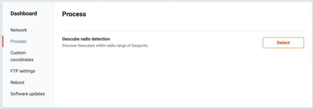
Process Page #
This page allows you to set up and manage your project.
Add a Geocube #
At any time, you can add an additional Geocube to your project. Simply click on the Detect button after selecting the nearby Geoport. This will launch a detection process and the Geoport will check all the nearby Geocubes and add the new ones.
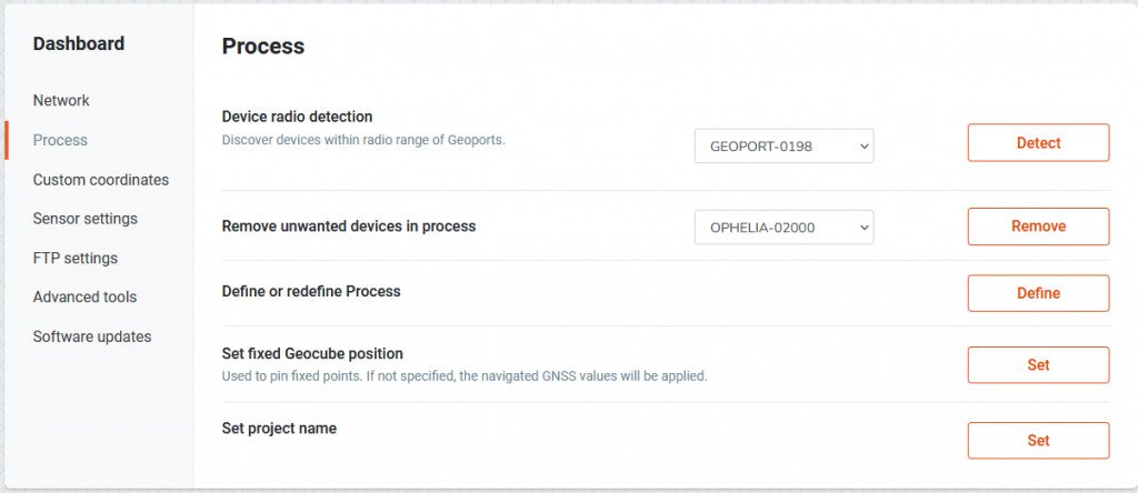
Remove a Geocube #
On the contrary, you can remove a Geocube from the process at any stage by selecting the desired Geocube and clicking on the Remove button. It will be removed from the interface. This does not affect the other Geocubes (provided you did not remove a fixed Geocube).
(Re)Define a Process #
You can also use the Define button to define or redefine the computation process. This screen will appear:
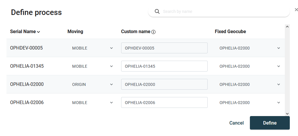
For setting the parameters of a monitored Geocube, choose the line containing its name, and choose the Mobile or Origin property in the drop-down menu in the Moving property column.
In addition, you will need to define which is the fixed Geocube associated with that particular Geocube. To do so, select the name of the related fixed Geocube in the drop-down menu in the Fixed Geocube column. By default, the first fixed Geocube on the list will be chosen, which means if you have only one fixed Geocube in your project, you can skip this stage. Please consult this page to get more information about using several fixed Geocubes.
You can also define a Custom Name for any Geocube. Custom names can only contain letters, numbers, dashes, and underscores. The custom name is considered a physical location. If you change the Geocube (thereby changing the serial name) but keep the same custom name, the computation will seamlessly continue and the graphs will display the positions of the current and previous Geocube on the same page.
If you change the Custom name of a Geocube, the system will consider it to be a new physical location and will therefore start plotting the graphs from the moment you defined that new name.
Click on Define, the computation process will immediately start. In normal conditions, it takes around 1 hour for a process to initially converge and start plotting precise positions.
Set the position of the fixed Geocube #
The Geocube system is very good at measuring displacement between fixed and mobile Geocubes. It is nevertheless not designed to provide a precise absolute position of the fixed Geocube. The Geocube system will naturally estimate the fixed Geocube’s position at the beginning of a process and keep that position for the rest of the project.
If you want to have access to precise absolute positions, you will need to precisely set the Fixed Geocube position. To do so, click on the Set fixed Geocube position.
Coordinates Page #
For operational reasons, you might want to visualize or download data with a projection that specifically meet your project requirements. The following screen will display:
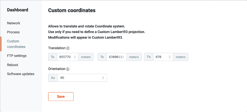
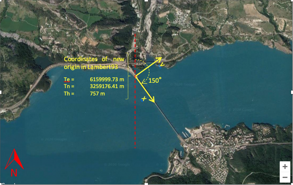
To center the projection on a given point, enter it’s coordinates in Te(East), Tn (North) and height, all being set in meters in Lambert93 coordinates.
Orientation is the azimuth between the North and the x axis, expressed in decimal degrees. In a regular Lambert93, x points in the East direction, which has an azimuth of 90° with the North.
You can change point of origin and orientation independently. If you wish to modify only one of them, leave the other unchanged.
Once parameters are set, press “Save”.